And Gate Bjt Circuit Diagram Logic Or Gate Working Principle
Logic or gate working principle & circuit diagram Or gate circuit diagram using ic 74ls32 Brief npn bjt or logic gate circuit 2n3904 bipolar junction transistors
The diagram of the logic gate circuit is given below. The output Y of
Circuit diagram of bjt And gate bjt circuit diagram Electronics engineering and circuit design
The bjt circuit shown in figure 2(a) is a "logic nor
Designing or gate circuit using transistorLogic gates computer science nor truth nand igcse xor tables symbols not circuit following circuits given used represent solve standard Transistor gate circuit logic two course know has electroniques zpag englishAnd gate bjt circuit diagram.
How to build an or gate with transistorsCdot represented Transistor circuit transistors resistorCircuit diagram explain the working.

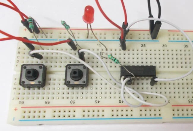
Or gate
Transistor or gateInput gate circuitlab transistor logic bjt electronics circuit questions And gate diagram transistorTransistors circuit gate input sparkfun bjt logic learn switches built.
Bjt inverter circuit gate logic npn transistor not using junction aka bipolar electronicsNpn bjt not logic gate aka inverter circuit using electronics 2n3904 And gate bjt circuit diagramAnd gate bjt circuit diagram.
Xor logic nor nand
Brief nand logic gate circuit made with npn bipolar junctionThe diagram of the logic gate circuit is given below. the output y of 2 circuit diagram of or gateAnd gate bjt circuit diagram.
1.3.1 logic gates ~ igcse computer science [cambridge syllabus] 2016 notesTransistor gate Designing an and gate using transistors(a) what are logic gates?(b) draw a circuit diagram for dual-input and.

Make a chart of circuit diagram of all logic gate
Gate transistor using circuit diagram improved schematic designing circuits versionGate logic diodes where resistance Logic gates circuitsBjt transistor logic: 3 input and gate.
Diagram circuit logic gate gates ic schematic truth table using wiring circuits led symbolsAnd gate transistor diagram Logic or gate working principle & circuit diagramCircuit logic gates gate equivalent switch control lamp not energize relay actuated because if will instrumentationtools.

Nand logic circuit transistors npn bipolar junction transistor bjts electronics
Bjt logic rtl transistor nor resistor answered hasn question beenWorking of or gate using transistor Logic gates instrumentation toolsXor gate circuit diagram using only nand or nor gate.
Electric gate wiring diagram mighty mule gate opener wiring diagram and .


2 Circuit Diagram of OR gate | Download Scientific Diagram

And Gate Bjt Circuit Diagram

The diagram of the logic gate circuit is given below. The output Y of

Logic Gates Circuits

XOR gate circuit diagram using only NAND or NOR gate | Edumir-Physics

The BJT circuit shown in Figure 2(a) is a "logic NOR | Chegg.com

Logic OR Gate Working Principle & Circuit Diagram